WPS FAQs
Frequently Asked Questions
(1) I am interested in a turbine for a single place helicopter... I am fascinated with turbines. What can you suggest?
(2) I have heard that the T62 (series) was built as a generator and its bearings aren't designed for the gyroscopic forces of a mobile application and perhaps this greatly decreases it's life. Have you taken this into account or re-engineered the bearings?
(3) Is there an established TBO for these motors?
(4) Can you run the T62/100 at 80% and get 80hp and burn 80% of the fuel (in other words) is fuel burn and power linear?
(5) I have heard one other thing about a limit on power (start) cycles... only so many times you can power them on and off before overhaul. Is this true?
(6) I heard that there is a particular rpm which creates a vibration similar to one of the (other) spinning parts within the motor, causing great stress and destroying the motor shortly there after. True or False?
(7) What would cause surging in a turbine and why?
(8) You have (re)engineered the turbines to have more horsepower. Would it be possible to (re)engineer it for LESS horsepower (70 - 80HP) and make it more fuel efficient?
(9) How well does the T62 handle rain/snow/ice/fog?
1) I am interested in a turbine for a single place helicopter... I am fascinated with turbines. What can you suggest?
Your small helicopter project is an excellent one, as are hovercraft, homebuilt aircraft of all types and many experimental vehicles. We developed these "Hybrids" specifically to satisfy those power-hungry requirements that a recip (piston) engine just could not provide at this size and weight level. Our main goal was to assemble an engine with the most concentrated amount of HP available in as small and lightweight a package as possible. There is no smoother running engine available... they run as smooth as an electric motor.
Top
2) I have heard that the T62 (series) was built as a generator and its bearings aren't designed for the gyroscopic forces of a mobile application and perhaps this greatly decreases it's life. Have you taken this into account or re-engineered the bearings?
While it is true that some of the near 100 "dash" number variants of these T62 turbines are in fact gensets, some are also "start compressors" or "hydraulic start units." Many of these variants are used specifically as an AIRCRAFT "on board" start engine or auxiliary hydraulic power for control surfaces. For example, the CH47 Chinook military helicopter currently uses them as a hydraulic start engine and the Cessna Citation III uses them as an APU. If the bearing design was ever suspect, they would certainly not be used in these aircraft. In fact, the bearing placement on these specific T62 variants is one of THE MOST reliable used. This is because NO bearings are located in the "hot section".
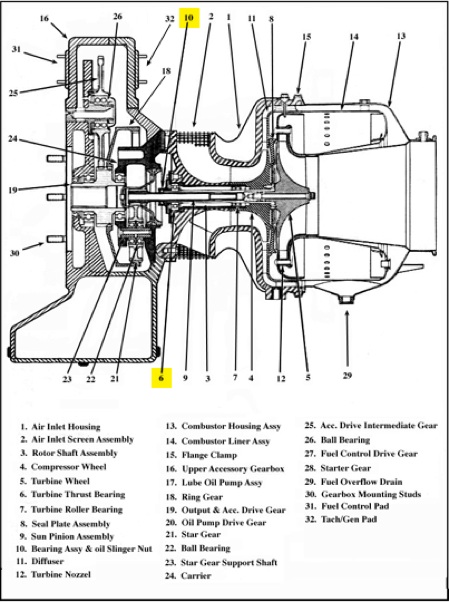
The rear-most bearing is a very sturdy ROLLER unit buried deep inside the nose of the compressor wheel, locating it at nearly the "center of mass" of the back-to-back compressor and turbine wheels. The front ball bearing (a high speed Barden unit) is located inside the gearbox at #10, right behind the slinger nut (see exploded view below).
This is called an "overhung design" with no bearings located in the hot section, providing little chance for them to wear out prematurely. This unique deeply recessed bearing location minimizes the “overhang,” causing no undue stress loads on wheels, bearings or shafts during engine maneuvering.
ADDITIONAL COMMENT: These high-speed turbine shaft bearings also have an "On Condition" Time Before Overhaul (TBO) life that can easily exceed 10,000 hours! The specs used in determining the wear of an existing bearing come directly from "Naval Air Rework Standards." Their manual, "Navair Standards 01-1A-503" specifically list pitting and rolling vibration limitations for the bearings in these turbines. If they do not meet the required criteria, they are discarded and replaced with bearings that do.
In the year 2000, a T62/150 turbine engine was installed in a fixed wing Luscombe and flown to Oshkosh as late as 2002. This Turbine Luscomb performs positive "G" acrobatics all the time! If the bearings or shafts were ever suspect, they would have failed long ago... or at least show some wear on last inspection.
There is a DIFFERENT variant of these Sunstrand/Turbomach/Solar units that also has a very high power output approaching 300HP, but it's much longer and heavier, and uses electronic controls (not the more reliable "electro-mechanical" units we use). Its rearmost bearing is NOT located "inside" the nose of the compressor wheel, but rather 2 inches out in FRONT of the compressor nose (almost a 3-inch swing). As you can imagine, this creates a far more exaggerated overhung bearing design, far outside the compressor and turbine wheel's "center of mass" (which is possibly the turbine being described). It's called a T62T40-LC1. The turbine shaft is much bigger to compensate for this bearing design, but the compressor and turbine wheels have twice the mass of a T62/150 wheel combination. It is still a very compact engine for this much power, but it is substantially longer because of the attached Load Compressor (the "LC" designation), which must be machined away.
For further proof of reliability, simply go to your local library and locate a 1972 or 1973 "Janes All the World's Aircraft" and look up “Solar,” you will find a listing of these very types of T62 turbines (100HP thru 200HP) in the beginning process of being certified for use as a “Primary Propulsion Engine.” This fact alone should answer your question very well.
3) Is there an established TBO for these motors?
We do not claim any specific Time Before Overhaul (TBO) for our "Hybrid" turbines, but here is some info as to reliability and/or maintenance on the original turbine power sections:
1) In the mid 60s, the T62/100 was originally rated at 2,000 hours when first developed and finalized.
2) In the mid 80s, the T62/100 was up-rated to approximately 9,000 hours, depending on which military service used them.
3) In the early 90s, they were further up-rated to "On Condition", which basically means "run until it wears out".
These ever increasing "TBOs" were a direct reflection on their exceptional longevity. Very little maintenance is required. Just change oil at regular intervals, ie: first 40 hours + every 25 hours after and/or annual (whichever comes first). Make sure all fuel and oil is fully filtered and clean before operating the turbine. Change fuel filters at the same time interval as oil filters.
About the only real wear item would be the gearbox on the higher power T62/150 and T62/190/230 HP turbines because of the increased input from these "Hybrid power sections." Since we haven't yet run over 2,000 hours with one of the "Hybrids", the gearbox should be visually inspected every 100 to 500 hours for wear... or incorporate "chip detectors" for automatic early warning of gear wear. The T62/150 Turbine Luscombe had over 130 flying hours (as of 8/1/00) and had no indicated turbine gearbox wear. Also, this "Turbine Luscombe" was on "oil analysis" since the day it was first run... and has not had any turbine gearbox "wear metal" show up in the oil analysis.
The T62/100 can be run at 100% power with a 100% duty cycle (continuous power). There are NO gearbox limitations with the T62/100. In fact, the gearbox can withstand 140+HP at a 100% duty cycle. Obviously, the T62/150 marginally skirts this conservative “military” limitation, but we have seen no wear even during continuous oil analysis on T62/150 powered aircraft (such as the Turbine Luscombe).
4) Can you run the T62/100 at 80% and get 80hp and burn 80% of the fuel (in other words) is fuel burn and power linear?
Fuel burn is rarely linear, but your example is actually close. If the T62/100 is run at lower power requirements, our findings show that power drops off faster than fuel burn. The factory fuel burn chart also shows this to be true. For example: The listed fuel consumption shows approximately 13.7gph fuel burn while producing 80HP... and approximately 16.1gph while producing 100HP on a standard temp day (59°F). That equals an approximate 15% reduction in fuel consumption while at the same time producing 20% less power. Although this exact same "relationship" will not exist at all Outside Air Temperatures (OAT), it should remain relatively close. The fuel burn rate while at flight idle, no load is about 6gph.
The only concern would be to know exactly where 80% power would be during all operating situations. Unfortunately, our Hybrid turbines do not have any provision for a "torque gauge." You simply use the temp gauge to set power. Obviously, max temps will provide max power on a standard temp day, but power can drop of by as much as 20% on very hot (100°F+), humid or high days. The max Turbine Outlet Temperature (TOT) for a T62/100 is 1090°F regardless of OAT. To produce a maximum of 80HP on a standard temp day (59°F OAT), exhaust temps should not exceed approximately 940°F. Still, the T62/100 would be well within your 80HP requirements on just about any normal day at or below 100°F.
ADDITIONAL COMMENT: FYI, Solar factory charts show OATs and the approximate power being produced at sea level, but there are no such charts with altitude included. The Turbine Luscombe was working on just that... an "empirical altitude chart" for the T62/150.
Also, the weight of the two different engines is very close, so the T62/150 would also fill your requirements, but at a higher cost. The T62/150 could also be "temperature limited" (flat rated) to just about any lower power level required. Obviously, the extra expense of a T62/150 would not be totally necessary for your requirements unless you're in a very hot/humid/high environment (over 100°F, above 8,000 ft. or combos of). We say this because we do have some "empirical data" from the Turbine Luscombe that may be extrapolated for the T62/100. For example, the Luscombe has shown the T62/150's power drop to be approx 25% while at 17,000 ft. This still gives about 110HP at max Exhaust Gas Temperature (EGT) (actually, TOT) while at that altitude. Nobody thought these little turbines would ever reach 15,000 ft., but the pilots say there is still power left at 17,000 ft. for even more altitude. In fact, we ALL thought these single-stage centrifugal turbines would surge (compressor stall) while in that rarefied air, but this has not been the case. All this and the Luscombe still climbs out at OVER 3500 fpm from sea level!
5) I have heard one other thing about a limit on power (start) cycles... only so many times you can power them on and off before overhaul. Is this true?
When these turbines were developed back in the 60s, their original intent was to have a 2,000-start "inspection limitation." Since they continually exceeded even this requirement with no visible wear, all subsequent start limitations were removed and only "On Condition" limitations remained. All armed forces (except the Air Force) and most current civilian uses of these turbine derivatives have ONLY the "On Condition" limitation (there are some civilian limitations of “just” 9,000 hours). The Air Force may still have a 2000 start "inspection limitation," but even at this inspection, the turbine is still under "On Condition" limitations, and can continue operation until the next 2000 start inspection. So, there are NO "cycle limitations" for any of the engines we have. As previously explained above, the gearbox in the higher power "Hybrids" will be the only limiting factor.
ADDITIONAL COMMENT: It is very possible that what was being described to you was the Garrett JFS-100 (90HP), which definitely DOES have a "cycle limitation." In fact, most JFS-100s do not even have an hour meter, only a start counter. I believe the cycle count for rebuild is 1,000 starts. The JFS-100 should NOT be used for continuous power because its oil system far too small and the operational Turbine Outlet Temperatures (TOT) to maintain 90HP are far too high. Some people are offering the JFS-100 with an increased oil capacity, but the "continuous power limitation" is NOT caused solely by the limited oil system. It is a very interesting TRUE "twin shaft" turbine, but the turbine wheels are also the limiting factor for continuous power. For the JFS-100 to make its rated 90HP, it must be operated at approximately 1400°F. This is just not possible for a reliable continuous power requirement. The turbine wheels may fail prematurely... and they are AXIAL, not radial, which means that when they fail, there is a very high probability they would "grenade."
Centrifugal wheels can also be made to fail, but they inherently have a far higher tolerance factor to "over temps" and "RPM excursions" because of their disk design (no free standing blades as in an axial turbine). There is a fairly extensive "question and answer" article circulating the internet that ALL small surplus turbines (modified, rebuilt or stock) should not be used in any homebuilt aircraft. Unfortunately, it does not specifically list the JFS-100, but the "descriptions" are clearly of this design. Actually, the JFS-100 could be used with an increased oil capacity, but the TOTs would have to be reduced to at or below 1200°F for reliable continuous operation. Our T62/150 runs at a "cool" 1180°F and the T62/100 at a even cooler 1090°F. Although, at these lower TOTs, the JFS-100's power would be reduced to approx 60HP or less, and it would still weigh the same as our "Hybrids". The Turbine Luscombe is easily proving that our type of "single shaft" turbines are indeed a fantastic alternative to piston engines... and a long-lived one at that.
FYI, the only failure we know of with our type of "single stage centrifugal turbines" (NOT built by us) was when an "experimenter" intentionally REMOVED the governor section of the FCU (Fuel Control Unit = fuel pump + governor). He did this so he could manually speed up the turbine shaft far past it's 61,000 RPM (100%) limitation. He was attempting to develop "thrust" from a T62-type shaft turbine engine by running it continuously at approximately 125%+ RPM (substantial thrust cannot be created with these small wheels, but that's another story altogether). It is estimated that during "hand throttling," an even higher 150%+ RPM excursion occurred causing the entire turbine wheel assembly to snap off at the rear "tie bolt," exiting the rear side of the engine. It purportedly spun for over two city blocks... running through bushes and fences until it finally stopped. Of note was that even after such a spectacular failure, it did not "grenade"... but it did wear down quite a bit! If it were balanced to our higher specs, it may have survived even that extreme overspeed (see balance info in Question 7).
Because a centrifugal turbine has a much stronger "blade disk design," it does not easily allow blades to explode off. These "single stage centrifugal" turbines can fail, but they generally fail with a loud screeching halt, not unlike an amplified “chalkboard scratch” as the bearings lock up from oil exhaustion, blockage or contamination. Generally, all that is seen is a hail of sparks out of the exhaust as the engine comes to a near immediate stop... with no substantial components leaving the engine.
Twin shaft turbines are definitely easier to couple to a drive system because the second "power turbine" (N2) is not physically coupled to the N1 gas producer shaft. It's similar to a hot gas "torque converter." The only problem is that to successfully operate a "twin shaft" turbine, you MUST have a second governor on the N2 section that controls the Fuel Control Unit (FCU) on the N1 gas producer. The little Garrett JFS-100 does not have a governed N2 power section, so you end up chasing N2 output RPM fluctuations with many required throttle corrections on the N1 "gas producer" (as your N2 load varies). Pilot Induced Oscillation (PIO) during throttle operation is a HUGE potential problem with this engine type. This would make throttling a JFS-100 installed in a small helicopter far more difficult to control than even a non-correlated piston-engine powered helicopter. As you pulled collective pitch or applied any rudder peddle effort (tail rotor yaw control)... or any load change for that matter... you would be substantially effecting N2 power turbine speeds, causing it to drop substantially, requiring more N1 gas producer throttle... and vice versa (which is where it would rapidly become difficult or dangerous).
Once our "single shaft" turbines reach 100% RPM, they STAY there! There are NO RPM fluctuations during ANY "power train" load variations on the craft (within HP limitations, of course). The FCU automatically handles all RPM and fuel supply requirements to maintain a STEADY 100%. This means that as you "pull pitch" or compensate for yaw, you do not roll in ANY additional throttle to compensate for load. Because of this, the pilot workload is tremendously reduced. This is exactly why a Bell JetRanger is so easy to fly... FAR easier than a Hughes/Schweizer 269/300 (and still much easier than a Robinson R22).
The only problem is that some type of “start clutch system” will be needed to interface a single-shaft turbine with an existing transmission. This clutch system would allow starting and a shutdown "cooling period" without load (neutral). For homebuilt helicopters, the lightest type of simple, manual locking "cone clutch" would be best. They are no bigger than a small coffee can, light and relatively low-cost.
Also worth noting, our Hybrid turbines can be operated to as much as 45 degrees from horizontal without problem... as long as the oil pickup is not ported to air (during low oil conditions)
6) I heard that there is a particular RPM which creates a vibration similar to one of the (other) spinning parts within the motor, causing great stress and destroying the motor shortly thereafter. True or False?
FALSE! There are no such vibration "harmonics" from any of our single-shaft "Hybrid" designs... or even from the original factory designs. If these problems ever existed, these turbines would never be certified for use in flying aircraft... as it is for the Boeing CH47 Chinook (military) and Cessna Citation III (civilian), just to name two well-known aircraft. We've not found that design flaw even with the JFS-100. If this were ever to occur, it could only be because one or more of the turbine wheels or high speed shafts were not properly balanced to at least factory specs. Vibration will simply not exist unless there is an unbalanced component. Also, vibration will NOT occur at some "magical" point. If it exists at all, it would start immediately at low speeds and increase in amplitude and frequency as RPMs increase. This negative information may be coming from one of the manufacturers trying to reduce or eliminate the use of any of their turbines in homebuilt aircraft.
ADDITIONAL COMMENT: Vibration by itself is far different from a "harmonic vibration." To make something vibrate harmonically in a gearbox would require that the spinning gears themselves be cut in a "repeating pattern," so the same heavy spot would phase in and out rhythmically with another gear or gears. We do not know of ANY turbine gearbox with an even number teeth on both the "drive" and "driven" gears (eg: a 12 and 28 tooth gear set)... which would be required to make them phase "harmonically"... and only then if out of balance. All turbine gearboxes are of NON-REPEATING gear patterns (eg: a 13 and 28 tooth gear set). This way, one tooth on the drive gear will NEVER mate with the same tooth on the driven gear on each successive revolution. This "non repeating pattern" also prevents wear occurring on any one gear tooth too rapidly. All drive and driven gear teeth share load with a different tooth on each revolution. This very normal (and old) gearbox design criteria PREVENTS the very "harmonic" vibrations these experts claim to exist.
Another thing to consider is that our Hybrid turbines are "Constant Speed Engines." There is no RPM "range" to harmonic through! ALL POWER is derived while at 100% RPM. Only "load" can be varied from 0% to 100% power. In fact, no or very minimal power should be applied when the turbine is at less than 100% RPM. To do so will likely cause an overtemp (depending on how much load is applied and at what % RPM).
Since these turbines are in fact "Constant Speed Engines," if there were any unbalanced components, there STILL would not be any "harmonic vibration phasing"... they would simply vibrate ALL THE TIME!
We have ALL our wheels (compressor, turbine and shaft) dynamically balanced to HALF the value required by the Solar factory specs. For example, the book calls for ".003 inch ounces" at a specific RPM, but we have them balanced to within .001 to .002 inch oz.s max, with the norm coming in at .0015 inch oz.s (half the factory requirement).
Actually, because of the increased level of dynamic balancing that we perform on our wheels, a higher maximum RPM limit could possibly be tolerated before you begin to cause damage from an overspeed... or even notice any perceivable vibration (though we certainly wouldn't deliberately overspeed any turbine to test this theory). Our completed turbines run very smooth. Even at standard factory specs, they're still smooth. In fact, you will likely run into much more perceivable vibration from several other airframe components like the transmission, clutch or driveshaft that were not previously noticeable with a vibrating piston engine. Remember, there are NO "power pulsations" either... only smooth continuous combustion which is much easier on any gear-reduction units, shafts, props or rotors.
7) What would cause surging in a turbine and why?
That can be a very extensive explanation. Here are some of the highlights. First, surging is literally a "stall," or more properly known as a "compressor stall." It is analogous to any other type of airfoil stall or loss of lift. If the incoming airflow remains constant and relatively laminar (with minimal or no blade flow separation), the compressor wheel will literally create "lift" and continue pumping air. Once a stall occurs, there is no more air flow coming from the compressor. The loss of flow leading to a stall can be caused simply by restricting the air inlet. This can easily be accomplished by improperly vented cowlings without enough inlet area. If cowled, we suggest at least TWICE the vented cowling inlet area as there is screened turbine inlet area to prevent any restrictions. A loss or restriction of airflow will slow the incoming air, causing an increase in the angle of attack and the tendency to stall, which basically leads right back to "loss of lift." It's just about the same whether you are talking about a wing or a turbine blade. Actually, any severe distortion of the incoming air can lead to a compressor stall.
Excessively overheated inlet air can also lead to a stall because of "air density" changes. High inlet temps cause lower effective pressure ratios, and lower power levels. Depending on load, these "single shaft" turbines will not likely become adversely affected with compressor stalls until inlet temps reach 180°F to 250°F (empirical). This is why it is very important to duct the turbine inlet to cool fresh air without any sharp edges and as few turns as possible. If cowled, the more venting the better. Each vent should be free-flowing with radiused entry lips preferred.
You can also have a loss of inlet airflow by a restriction in the compressor DISCHARGE diffuser, which is why it is so important to perform a "compressor wash" on a regular basis... especially if operated in a dirty environment. Also, if too much fuel is introduced during a start or an acceleration sequence (or too early), compressor discharge pressures will increase, possibly leading to a stall. This can be caused by improper "fuel scheduling" from a maladjusted or improperly modified Fuel Control Unit (FCU). All our FCUs are fully adjusted to allow throttling from "Ground Idle" (or "Flight Idle") of approx 64% RPM to 100% RPM. FYI, these were originally one-speed turbine engines at 100% RPM.
ADDITIONAL COMMENTS: You may have noticed that our MPEG Start Video does indeed show an improper "stuttering surge" with a HUGE flame just prior to reaching ground idle. We wanted to create a spectacularFLAMING START video on our website. We succeeded in artifically creating the "flame affect" (truly, successive compressor stalls) by first starting the turbine and immediately aborting the start just prior to the ignition point, but without disabling the fuel solenoids as well. What this did was load up the burner with enough excessive fuel so when we initiated another immediate start sequence (before the excess fuel drained out of the relief valve), we would have accomplished the same effect as mentioned above (ie., too much fuel/fuel introduced too early). We got the desired effect, but surprisingly, no one has ever mentioned it to us... even some "turbine experts" have missed it (though, maybe not all).
Another way to cause a stall (and flame out) is to rapidly reduce the throttle from 100% RPM to 64% Flight Idle. What this does is allow a pressure differential to be created between the burner (combustion chamber) and the compressor inlet to the burner. If RPM is reduced too rapidly, the pressure drop at the compressor outlet will allow the greater pressure accumulated in the burner to "backup" and decrease any further airflow through the compressor, literally "choking" the turbine... and also cause a rapid "flame out" (which you'll note we also did in our video, along with an immediate "relight"). Power (load) must be backed off slowly or the turbine may stall and flame out. Throttle controls should be properly set up on any aircraft to avoid this situation.
8) You have (re)engineered the turbines to have more horsepower. Would it be possible to (re)engineer it for LESS horsepower (70 - 80HP) and make it more fuel efficient?
This is actually unnecessary. There is a 75HP variant, but it weighs exactly the same as the 100 and has a much higher 8000 RPM main gearbox (and is more costly to find and modify). The major changes in the 75HP variant were a more restrictive "compressor diffuser" (similar to a reduced intake manifold passage on a piston engine), and a matching restrictive "turbine nozzle" (similar to a smaller exhaust port).
The only engineering required for the current 100HP engine is to "flat rate" the existing T62/100 by printing a redline at a lower temp on the Turbine Outlet Temperature (TOT) gauge. Actually, a "double redline" would be best (for the extremes in Outside Air Temperature (OAT) range while at sea level). One redline for operation at say 40°F OAT and another for 90°F. They wouldn't be that far apart, so it would be easy to mentally assess where that day's TOT limit would be by eye (always within that "Redline Range" at sea level). Also, flat rating the T62/100 to 80HP would allow it to develop a full 80HP during hot, humid or high conditions. These same extreme conditions would reduce the 75HP variant to far less than your power requirement (possibly as low as 50HP). So, the T62/100's Fuel Control Unit (FCU) cannot be re-adjusted to limit power, but by simply adding a "red line," the problem is easily solved.
9) How well does the T62 handle rain/snow/ice/fog?
ANSWER: Not much differently than any other air-breathing engine. Moisture (humidity) in the atmosphere will generally reduce power. If the snow does not melt and get ingested as water vapor, the incoming air will actually remain very dry. The drier the air, the more HP that an engine will produce (without fuel augmentation... see below). So, snow won't "put out the flame"... unless it blocks the inlet. If the inlet does get blocked, you will see first hand what a true compressor stall is!
ADDITIONAL COMMENTS: Actually, on an overly hot day (100°F+), a turbine's Turbine Outlet Temperature (TOT) and Turbine Inlet Temperature (TIT) can be reduced by water injection to prevent it from "temping out." Further yet, they can be "power augmented" by a mixture of water/alcohol (methanol) using a 2:1 ratio. What occurs with the water/alcohol "mix" is that the alcohol acts as an additional fuel that would normally raise the TIT/TOTs to excessive levels, but the addition of water in the mix prevents a temp climb. It's similar to the power effects of nitrous oxide injection in a piston engine, without any of the dangers (ie., explosions). Once the cooling component (water) runs out, so does the extra fuel (alcohol)... and the turbine settles back to normal power output on only the original jet fuel. Obviously, once this "mix" is gone (or shut off), you must immediately reduce power or you may cause an overtemp condition to exist.
This is the exact procedure used on the early Bell 206L JetRangers. They had a standard 400HP C20 that did not have enough power to lift the ship into a hover on hot days at max gross weight (not the normal 640HP C30s used in today's "Ls"). If you can't get a helicopter into a normal hover, it can't easily fly. Yes, you can drag the skids to try to get forward speed initiated, but that's not "normal." Bell incorporated a large enough tank of water/alcohol to allow several "hot takeoffs" with this simple power augmentation method.
A nice side benefit is that the compressor section is being lightly "washed" at the same time. The only problem is the limited supply of "mix" you can keep onboard in a separate tank. Only distilled water should be used or heavy deposits can begin to form, possibly leading to a compressor stall. The water mix must then be delivered in a very fine spray or compressor wheel erosion can occur. The best way is to use compressor "bleed air" to pressurize a water/alcohol tank. About 35psi can be found at max power from the compressor. Simply control the "liquid line" with a switch armed solenoid valve. Then direct two or more fine spray nozzles towards the turbine inlet... and that's it! A simple "sight gauge" would be all that's needed to know when to disable the solenoid valve and manually reduce load.
Actually, water will not entirely damage a running turbine engine as it could a piston engine (as long as no "liquid water" is dumped in while running). "Compressor washing" is accomplished using water by first removing the igniter power source, disabling all fuel solenoids, and then spinning the turbine up to "start RPM" while introducing a light stream of (preferably) distilled water directly into the compressor inlet. The fine mist required for injection under power is not necessary since the RPMs are much reduced. Only 15 to 30 seconds of starter run time is required to wash the turbine's insides... and it does a really good cleaning job. Also, finely ground walnut shells can be thrown in while the turbine is running with fuel... at flight idle, of course (makes really neat fireworks!)